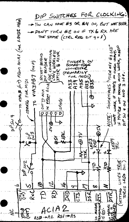
DIP switches:
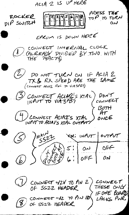
DIP switches:

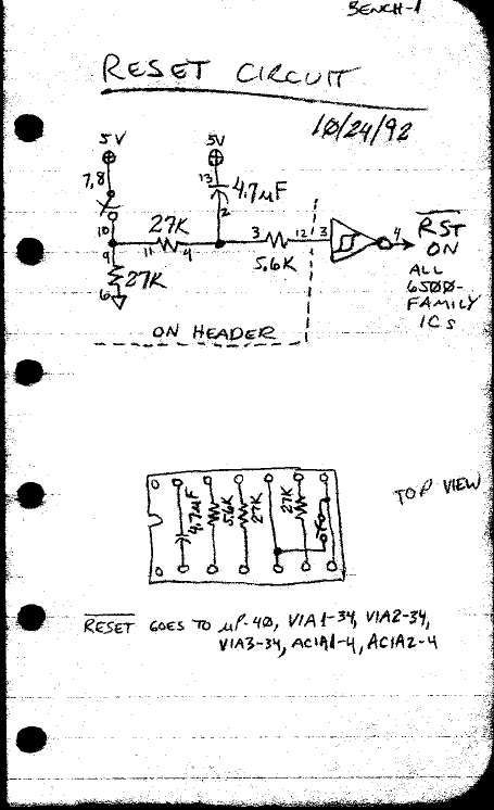
reset circuit:
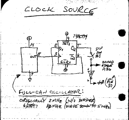
clock source:
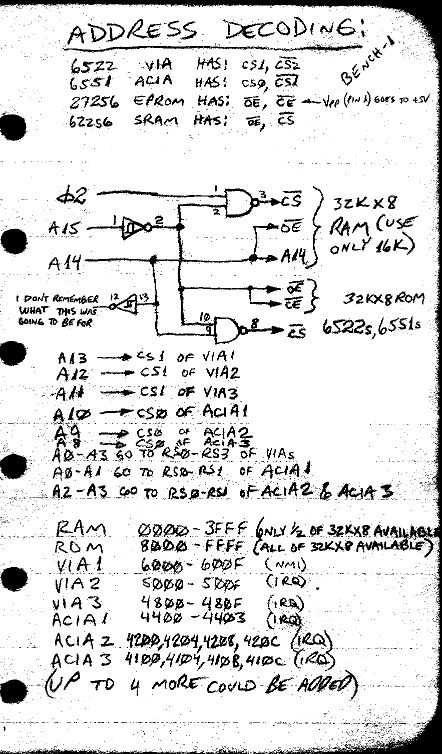
address decoding:
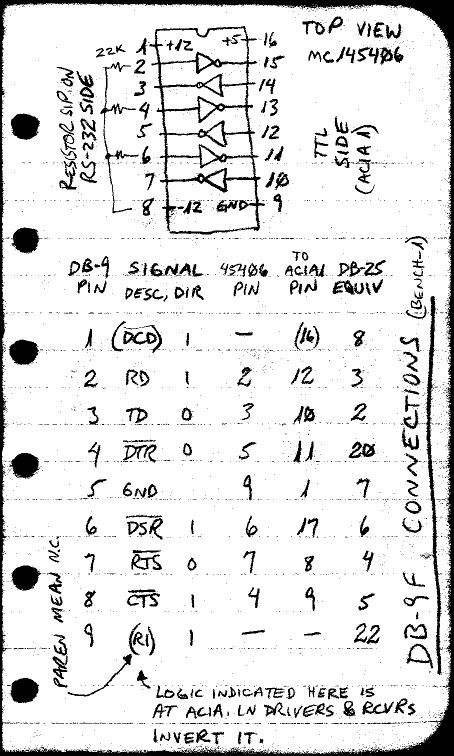
DE-9F connections, for main RS-232:
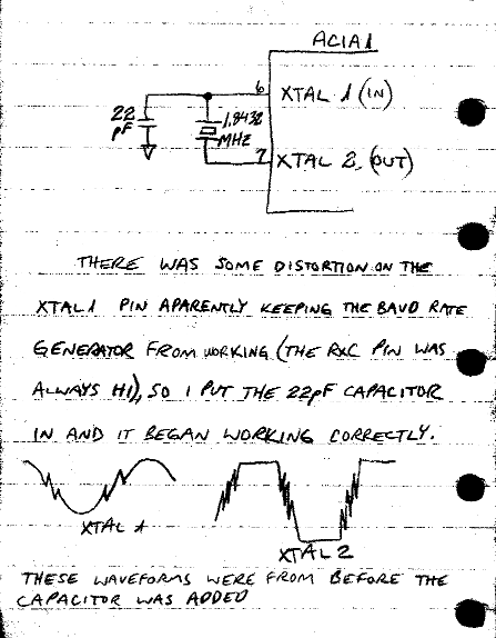
ACIA1 crystal circuit:
ACIA2 circuit (primarily for MIDI and Lynx wireless connections)
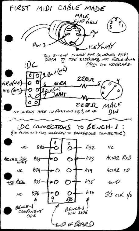
MIDI cable to musical keyboard:
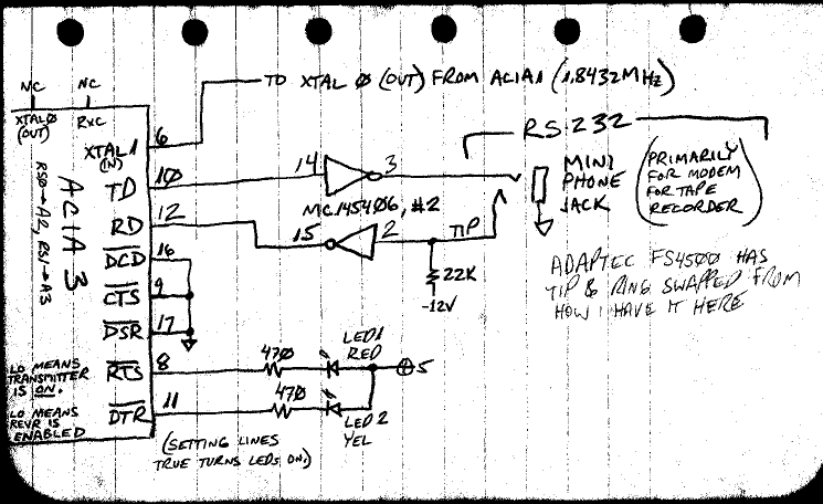
ACIA3 circuit (which was intended for tape modem, which is now obsolete):
A/D converter circuit:
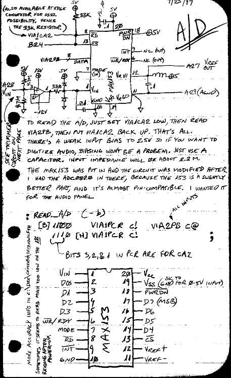
There's another page farther down showing how this is connected to the outside world.
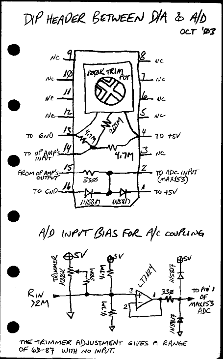
DIP header for A/D's op amp parts:
D/A converter circuit:
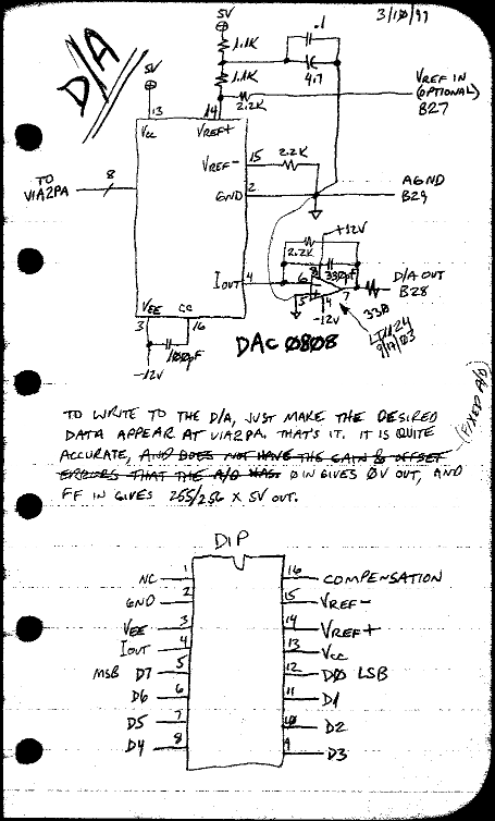
There's another page farther down showing how this is connected to the outside world.
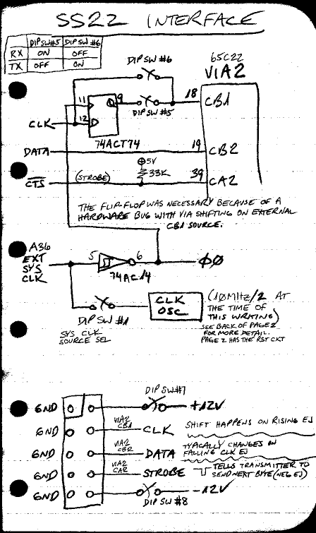
SS22 interface:
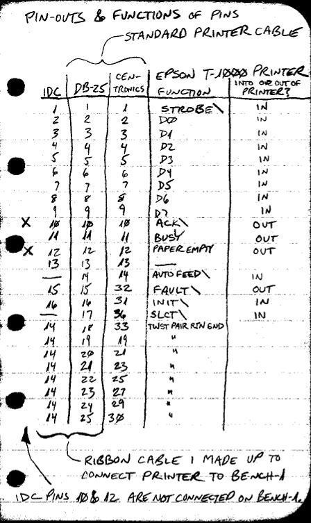
parallel printer connector pinout:
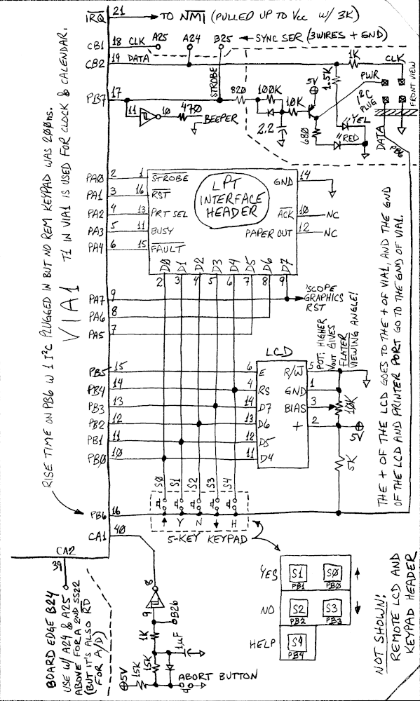
the mass of stuff interfaced via VIA1
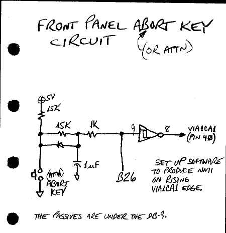
From top to bottom: NMI is used with T1 for realtime clock & calendar plus Abort key circuit (shown at the bottom); then
there's a synchronous-serial port, beeper, I²C, printer, LCD, keypad, and Abort circuit:
front panel layout:
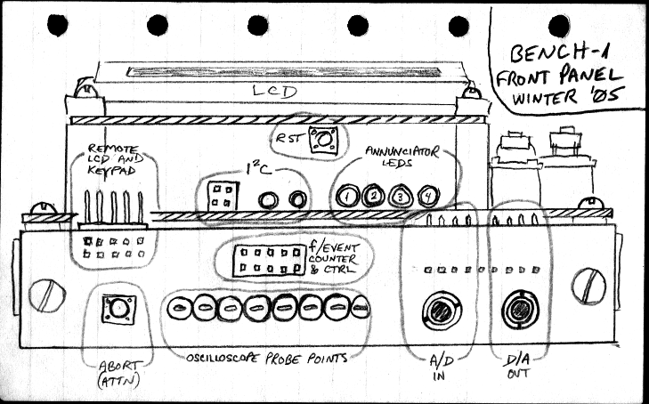
The round A/D and D/A connectors are 3.5mm 3-conductor jacks.
The four larger annunciator LEDs here are turned on and off by software, so you can use them to monitor where you are in
a program. In Forth, you can use lines like
TURN ON #2 LED
or
TURN OFF #4 LED
where TURN is a variable, ON sets it to $FFFF
and OFF clears it, #2 and #4 are
the names of constants made to be 2 and 4, and LED turns the named LED on or off according to
what's in variable TURN. The #4 LED feed is also brought out to one of the oscilloscope
probe points on the front so you can use it to trigger a sweep as you watch another circuit, or just watch something
that's too fast to see flashing.
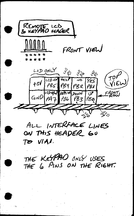
remote LCD and keypad header:
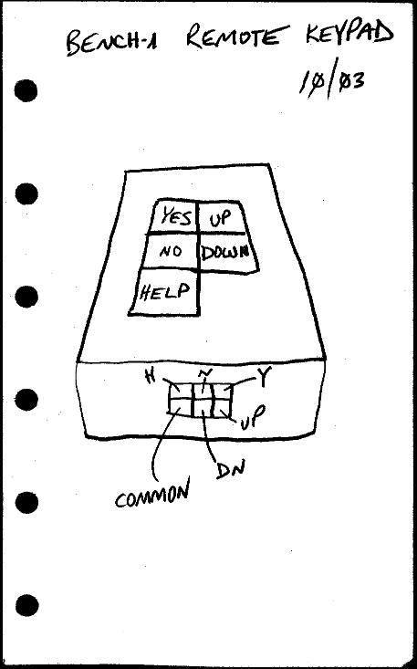
remote keypad diagram:
front-panel Abort key circuit:
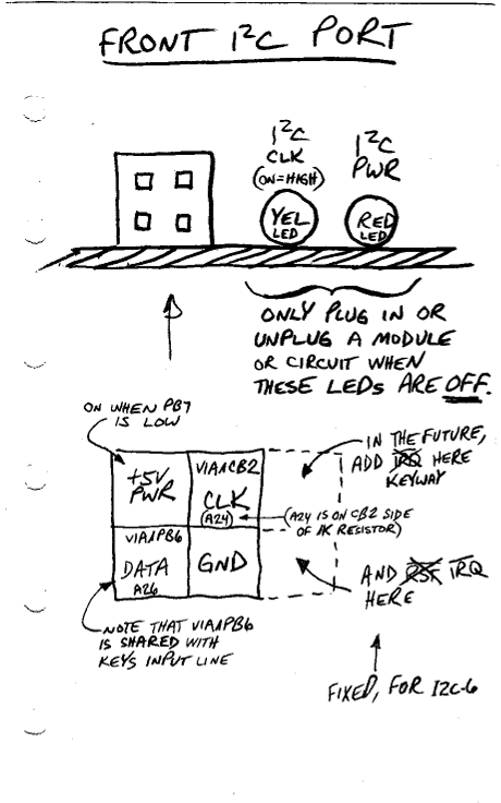
front-panel I²C port (compatible with
I2C-6, but this was before we added I2C-6's
interrupt pin and keyway):
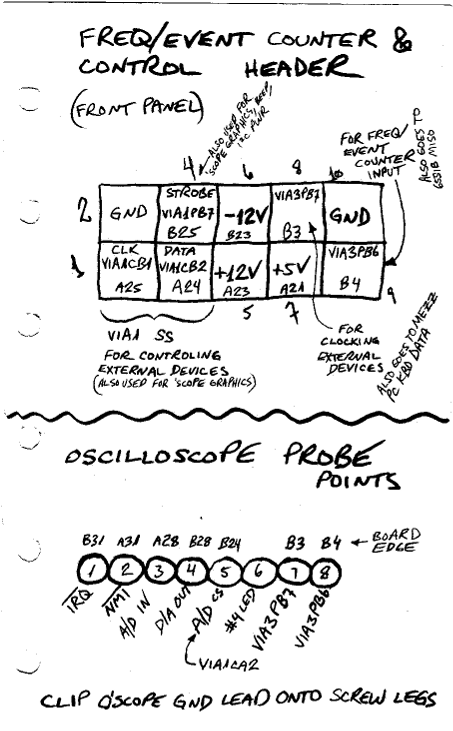
front-panel frequency/event counter & control header:
D/A anti-alias filter socket, and front-panel D/A connections:
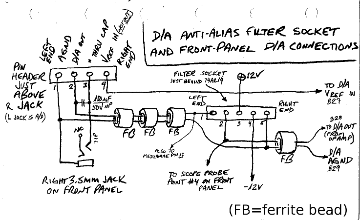
(This is the page shown in the picture at the end of the main web page about workbench computers.)
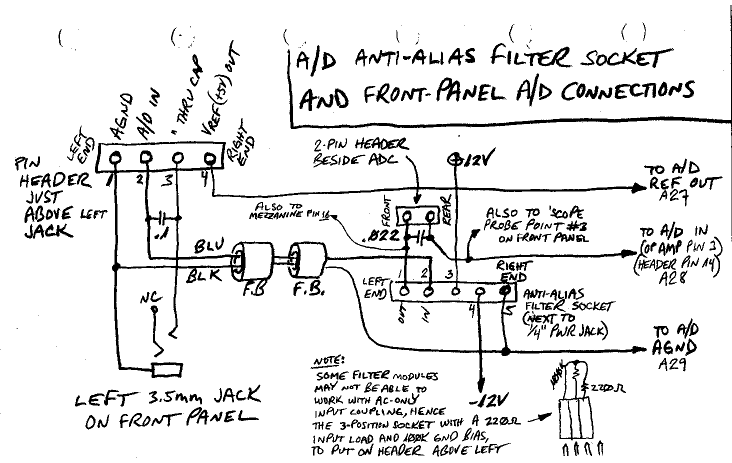
A/D anti-alias filter socket, and front-panel A/D connections:
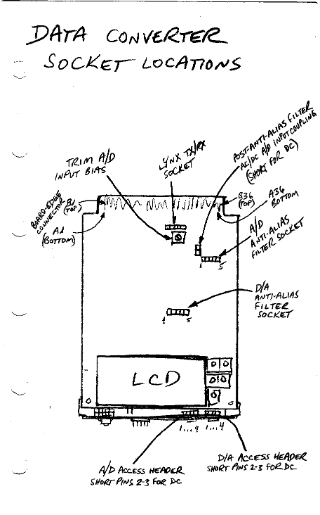
data converter socket locations:
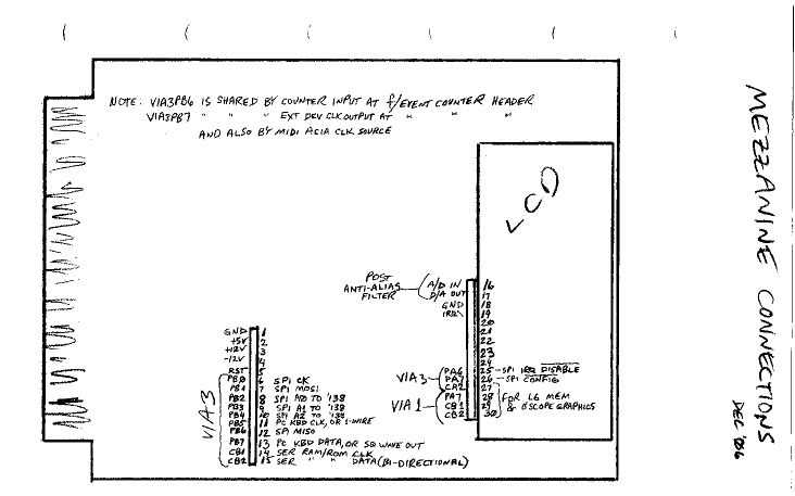
mezzanine connections:
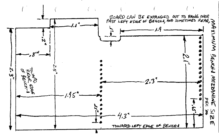
maximum mezzanine dimensions:
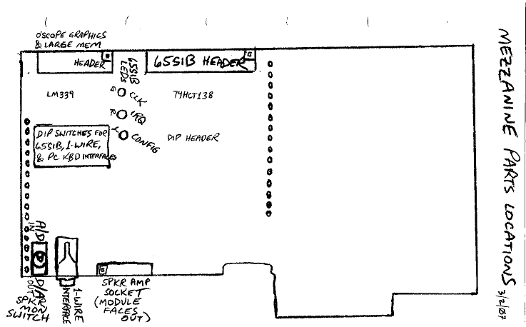
mezzanine parts locations:
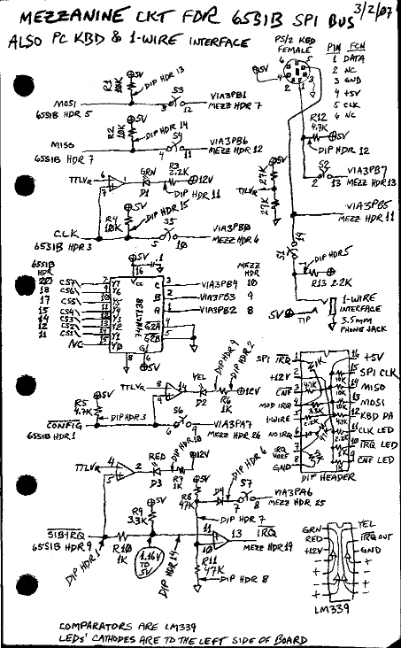
mezzanine circuit for 65SIB, also
PC keyboard and Dallas Semiconductor's (Dallas in now part of Maxim) 1-Wire interface:
I should have put a DIP switch on one of the 138's E inputs so an
uninitialized VIA3PB doesn't enable anything, and S7 (switch 7) should optionally disable IRQs by shorting D4-A to ground.
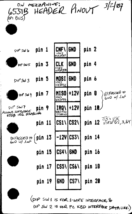
65SIB header pinout on mezzanine:
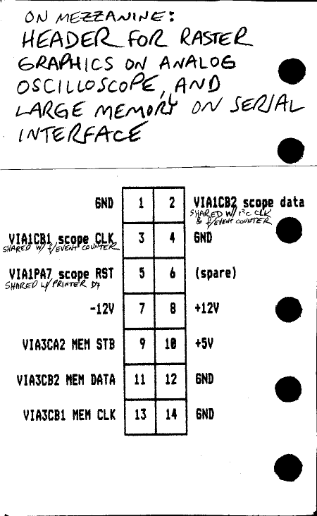
mezzanine header for raster graphics on
an analog oscilloscope and for large memory on a serial interface:
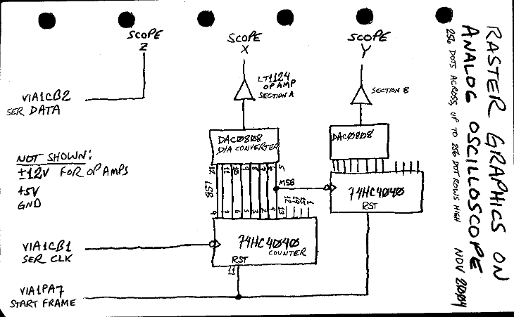
raster graphics on an analog oscilloscope, circuit built up on a separate board, not on Bench-1:
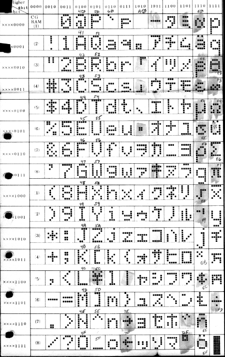
LCD characters. This page is cut out from a data sheet, and needed to be folded to fit in the tiny ring binder.
other side of the LCD character page, showing instructions:
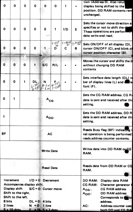
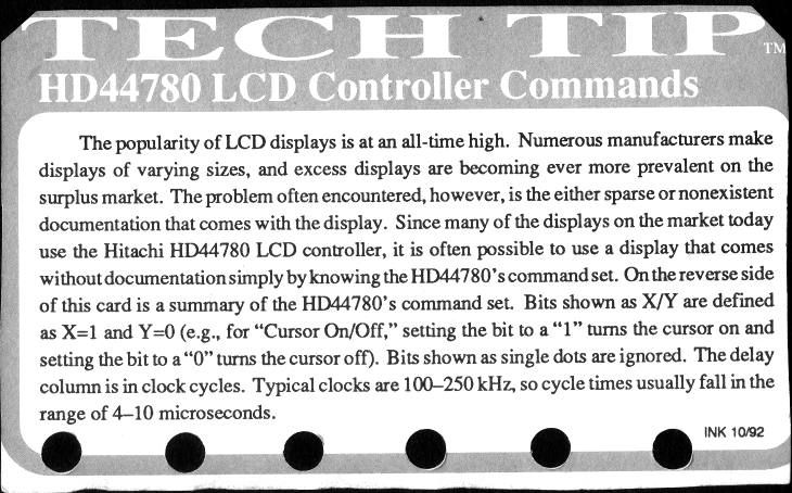
LCD instructions, put another way:
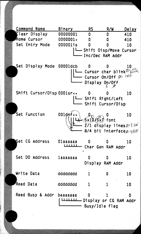
and other side:
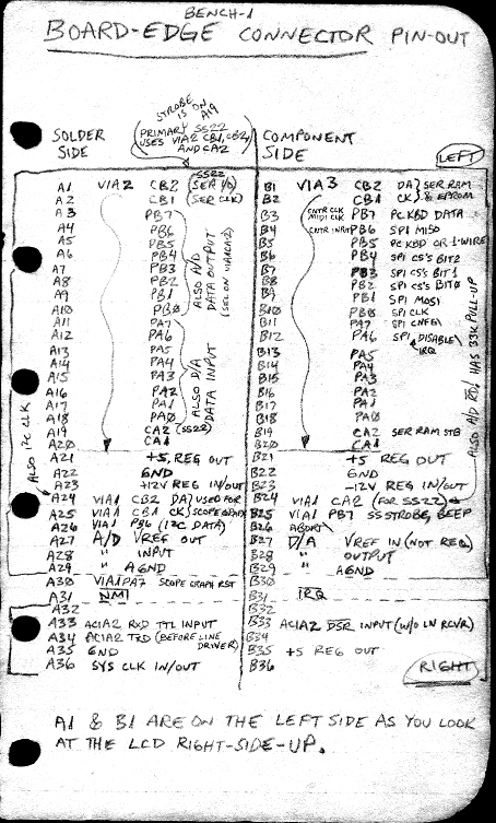
board-edge connector pinout:
regulator circuit:
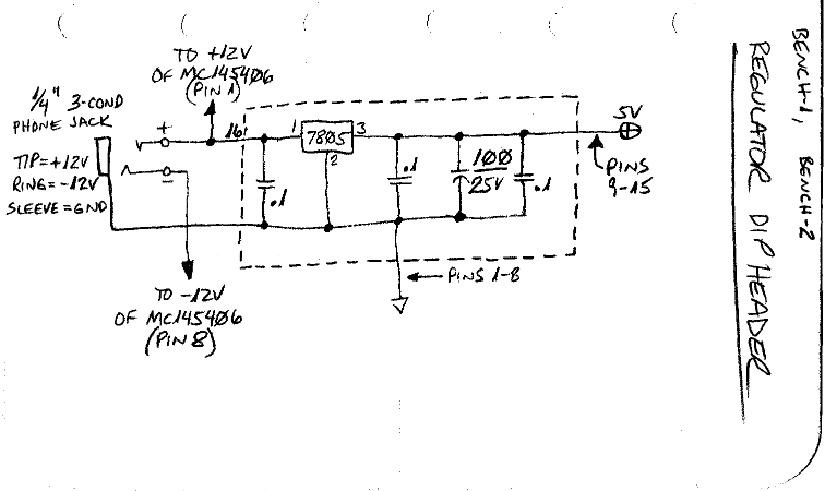
The .25" 3-conductor phone jack for power was not a very good choice. I'm not sure what the best would be; but there are a lot of things that need a higher plus and minus voltage (rather than just +5V or +3.3V), so unless you convert the voltage on the board itself with switching regulators, I still suggest using a plus and minus input, like ±10V. The exact voltage is not critical at all for most things. I use it to power: