Many have asked about the workbench computer which I have used as a "Swiss Army knife" of the workbench, for
both work and play. Since 1985, my work has been in the design and testing of aircraft communications devices,
mostly for private pilots, but now also for military, law enforcement,
medevac, and other fields. What
I have in the relevant project page on
6502.org is quite outdated and not very detailed. Here I will try to update and fill in, and to tell about other
workbench computers too, past and future.
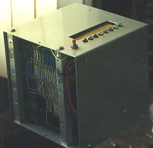
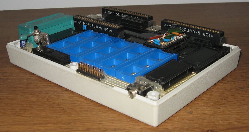
In its original form, I built "Bench-1," wire-wrapped, on a 4½"x6½" perfboard, late in 1992 to meet a need on the workbench for things like:
The workbench computer does the job of a lot of other equipment, just as a smartphone today does the job of camera, tape
recorder, telephone, radio, TV, and more. I have made a lot of improvements to Bench-1 over the years, which have
delayed the need for a replacement I've talked for years about making (and the mezzanine, visible in the second picture
above, still has room for further additions). I call it "Bench-1" because it was my first successful effort at a
workbench computer. (The more-limited
Bench-2 has been in service for years too,
and others, will be discussed further down.)
Most I/O goes through these three VIAs. VIA1 handles the:
Note how many things a single VIA can do at once! VIA1's IRQ output is the only thing on the processor's NMI input.
VIA2 and VIA3 are mostly available for user projects except when using the following. Usually I have all the needed I/O; but once in a while I wouldn't mind having one more VIA. The need for more is rare.
VIA2 and VIA3, as well as all three ACIAs (below) are on the processor's IRQ input.
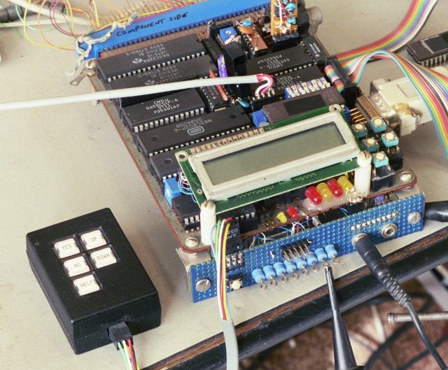
Here it is being used in the development of software for an aircraft audio panel's front panel which had two gray-code rotary switches for selecting functions, LCD (barely visible, behind and to the left), lots of tactile switches and LEDs, and an ambient light sensor, before I had added the mezzanine or front connections to the workbench computer:
Interfacing to the breadboards was through the edge connector at the back, which I have found through experience is usually not as practical as using the many other smaller connectors on the computer.
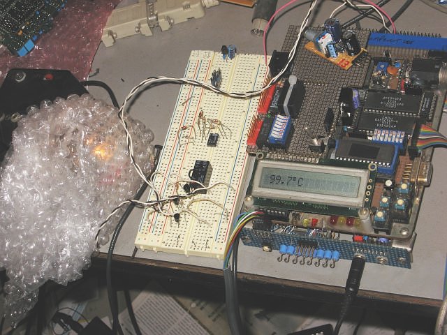
Below, I was keeping an audio jack under mechanical tension in 100°C for three days, to make sure it would not deform in an aircraft parked on the tarmac in Phoenix in the summer. The oven consisted of an incandescent light bulb in a small jar insulated with bubble wrap. The workbench computer watched the temperature, and by using the relay on the solderless breadboard to turn the bulb off and on, could set the "oven" to the temperature I dictated (within a fraction of a degree, and here you see it at 99.7°C instead of 100). The 3.5mm plug plugged into the front of the computer comes from the temperature sensor and is plugged into an A/D (analog-to-digital) converter input jack. The temperature sensor was an LM335 in a TO-92 package. The black project box at the extreme left of the picture has the signal-conditioning and calibration circuits for three LM335's.
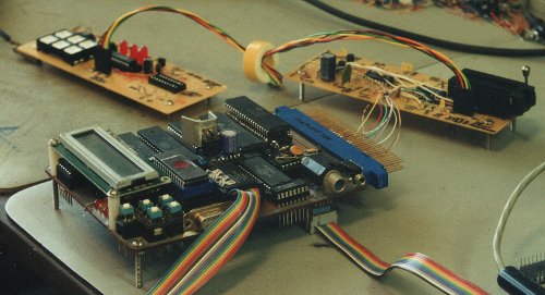
The picture below shows my PIC programmer (top right), connected to a prototype board I was using to develop
something—I can't remember exactly what anymore, but it wasn't necessary to breadboard all the audio circuitry,
only the part to test the digital controls. This again was before the mezzanine and front panel were added.
Here's an incomplete list of things I've used the workbench computer for:
I've used it to substitute for expensive equipment I didn't have. Sometimes it's worth the extra overhead
when you're not going to do it often enough to learn complex tools. I've done that kind of thing many times, for
example when a required $5000+ lab instrument might take only a few minutes to set up (after you're familiar with it) but
it's late Thursday afternoon and I want to get the job done, and there's no way I can research and rent the equipment and
have it here before Monday or Tuesday, so I use Bench-1 to jury-rig the same functions. It may take me all day Friday
and Saturday to breadboard a supporting circuit and write the program for it, but then I can have an answer for the boss in
his email in-basket when he gets into the office on Monday morning. If I ever need the same thing again, the
breadboard is there and the program is written.
Bench-1's EPROM has a Forth kernel including an assembler and lot of extras. A host computer sends instructions as plain text, over a serial line, which the Forth takes in and interprets, compiles, or assembles, on the fly, as appropriate. Forth allows writing a new code fragment and trying it instantly, with no need to recompile your whole application to integrate it. It becomes part of the language, even though it goes into RAM, not ROM.
The host computer can be anything that can send the text over RS-232; but it should have a worthy text editor for editing and saving source-code files, and be able to send out a marked block of raw text that could be as short as one character or as long as many pages. The OS doesn't matter, and the host itself does not normally do any compiling or assembling. It only handles source-code text. The editor is never suspended or backgrounded during development, nor does the host need to multitask.
I use an old DOS PC running the MultiEdit professional programmer's text editor and 132-column display, and I've had up to 36 files open at once, windowed and tiled various ways. I've also used my HP-71B hand-held computer as a host. The host computer is not running a terminal emulator or any TSRs or anything special. It just thinks it's sending the block of text to a serial line printer. The workbench computer just thinks the RS-232 link is from an RS-232 keyboard and that you're a lightning-fast typist who never makes a mistake.
It's hard for people to understand just how simple this is when I demonstrate it. Maybe some day I'll be able to post a video. It is possible to have the host computer assemble code and then send Intel Hex code for the workbench computer to take in, but that's not the normal way. Bench-1 can compile Forth source code and assemble assembly language source code.
Workbench computer output is normally signals and controls on the workbench; but there does need to be some human-readable output too, hence the LCD. There are four LEDs on the front for software-controlled status indication, plus eight probe points for oscilloscope probe access like for oscilloscope triggering. There's a piezoelectric beeper, and there's an amplifier to feed a speaker with either the A/D input or D/A output signal, switch-selectable. In the rare situation that I need to send data back to the host PC, that can go back via the RS-232 as well. If I need to print, Bench-1 has its own printer port. Material to be printed does not need to go back to the host computer.
Sometimes a few keys are needed on the workbench computer. Bench-1 has five keys which can be used for anything you arrange in the software; but their usual functions are:
| Yes Enter Continue |
Up |
| No Cancel Exit |
Down |
| Help Menu Edit |
The host PC is on a desk that's separate from the workbench, and sometimes I want to be able to press buttons or see the
LCD without getting up and stepping over. Bench-1 has a connector for a remote keypad and LCD.
When I worked in applications engineering at a VHF/UHF power transistor manufacturer in 1984-85, having an
ultra-portable hand-held unit to control repetitive test processes became quite attractive. The HP-41cx
calculator/computer fit the bill, with its vast capability to interface to all kinds of lab equipment, through the HP-IL
interface method and interface converters to IEEE-488 (HP-IB), parallel, and RS-232. It could be taken from your
desk to your workbench and back, much more easily than laptops (which didn't really exist yet), go in your brief case to
go home, etc..
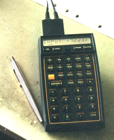
In 1986 I was the only engineer working at a much smaller company. Having gotten an HP-41cx by then, I set up our first automated testing of products with it, using a 20-page program and a half-dozen files. Yes, this calc has a file system, text editor, boolean functions, base conversions, and other things people didn't expect on a calc in the mid-1980's, and the I/O programming on it was much easier than doing it on a PC. People would nearly wet their pants when they saw a hand-held unit controlling a stack of lab test equipment. :D
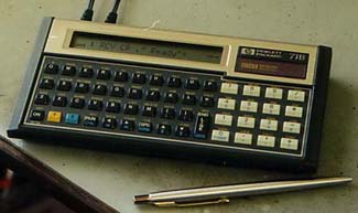 Later I stepped up to the HP-71B
hand-held computer (mentioned earlier, and shown at right) which was much faster, and directly addressed half a megabyte
of memory back when desktop computers usually had 64K.
Later I stepped up to the HP-71B
hand-held computer (mentioned earlier, and shown at right) which was much faster, and directly addressed half a megabyte
of memory back when desktop computers usually had 64K.
The thick, hard-bound test equipment catalog that came every year from Hewlett-Packard (later spun off as Agilent, and now Keysight) was full of great equipment to drool over; but most of the products were thousands of dollars, too pricey for a tiny startup or home office to be buying unless the business depends on constant use of it. I also started needing much greater speed than I could get with the calculator.
Sure, these hand-helds let you do bit-twiddling on the interfaces, do shifts, rotates, and program in assembly as well, but they were hopelessly slow for some of the things I wanted to do that were far beyond just sending a command to a programmable power supply to put out 9V with a 100mA current limit, telling a signal generator to give me a 4kHz sine wave at 160mV, telling a relay box to route certain signal paths, and telling a DMM to go to a certain range and mode and take a reading. Even the HP-71B shown here, which was much faster than the HP-41cx shown above, topped out at 5,000 bytes per second on the HP-IL interface. (For comparison, I've had Bench-1 service up to 140,000 interrupts per second, handling a byte with each one— and future workbench computers will be many times as fast.)
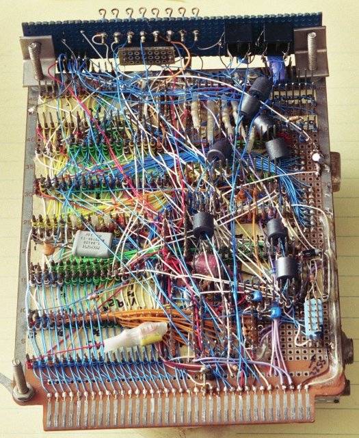
It didn't take a genius to figure out that one could breadboard a computer with plenty of general-purpose I/O plus A/D and D/A converters to do some of the same jobs the big, expensive equipment did. I was not totally new to 6502 computer construction, as I had made a computer in 1985 which worked but was not useful (shown here)
and later a couple of 65c02 computers for work, to help private pilots with their navigation. One of them went
into production although only briefly because assembly was too labor-intensive due to poor packaging design by an
outside service. (Sorry—I don't have any pictures of those.)
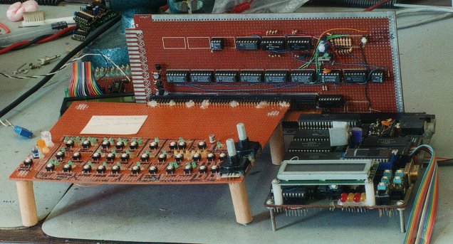
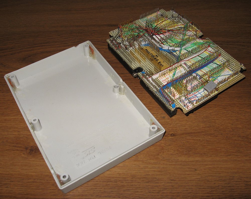
I still wanted very much to make such a computer in a tough case that could be thrown in my brief case. One of my false starts, from approximately 1989, is shown here, beside Bench-1 which came a few years later:
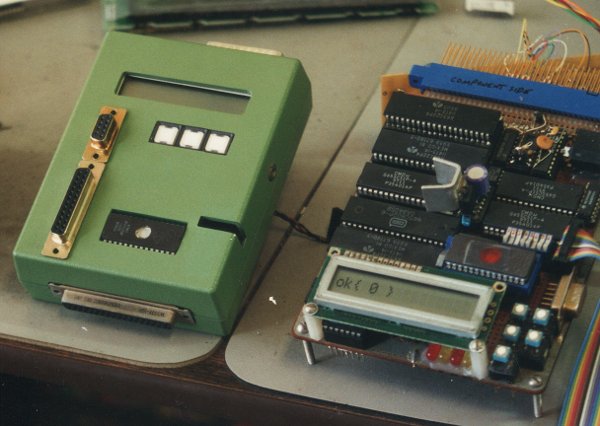
There was a DB-25 connector top end for the printer port, a 37 on the bottom end for general-purpose I/O, mini phone jacks on the sides for power and modem, a couple more D-sub connectors on the front (I don't remember what they were going to be for), and the minimal LCD and 3-key keypad. The EPROM and the lever for its ZIF socket were accessible without opening the case, for easy change-out for different applications. ABS plastic is wonderful stuff for cutting and milling and tapping and gluing at home. My ideas for this computer outpaced my progress though, and before I got very far, I could see that everything I wanted would not fit, as I was limited to DIPs and wire-wrap at the time. I started over with a bigger box:
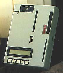
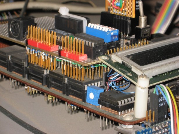
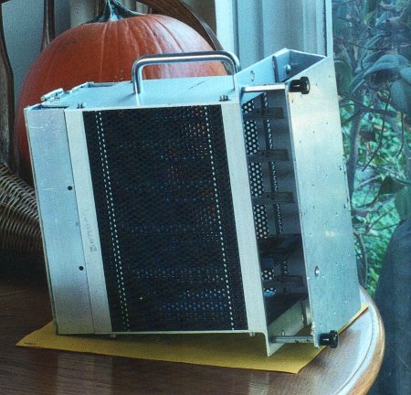
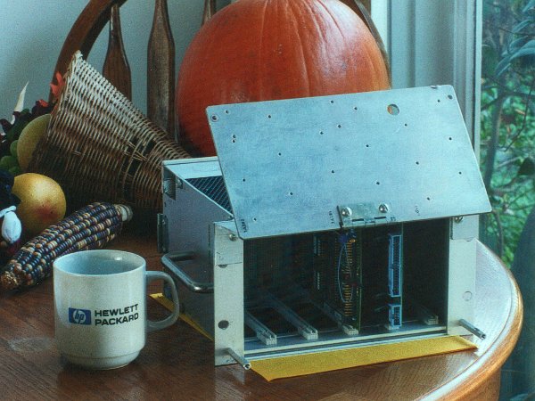
You can see the quick-change EPROM idea again, and the Reset button just below it. There's an octal DIP switch also accessible from the outside, and an annunciator LED bar. The long slots were for plugging 44-contact boards (in the same form factor as this one) into the edge connectors inside, which you see in the next picture. The top two slots should have been the same width as the bottom one.
This time I nearly finished. Why I didn't, I don't remember. Late in 1992, I had to quit contemplating,
and make something work. I had an immediate need, and I responded by throwing the portability and nice case idea
out the window and making Bench-1 which was totally exposed. It has served now for 25 years at the time of this
writing.
One of Bench-1's deficiencies is lack of portability. Its wire-wrap pins underneath, plus things like
unprotected connector pins, oscilloscope probe points, the unsupported tops of the LCD and plug-in modules make it very
vulnerable to damage if I were not careful transporting it, and especially if I were to try to use it portably, like to
take data in an airplane for testing for our aircraft products. The next one, Bench-3, should be able to work with
internal batteries, have an internal speaker, and be able to load and operate software without a host computer helping.
Then there's the obvious stuff, that I would like:
I've gotten a couple more ABS boxes that were bigger and of different layout, to try again, but couldn't figure out how to get past a couple of the packaging hurdles, where I need access to a lot of connectors, be able to swap out anti-alias filter modules without using a screwdriver, etc.. Someone gave me a beautiful two-tone blue steel case, but again I had the same problem.
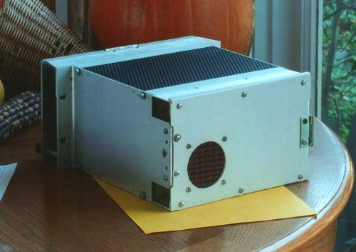
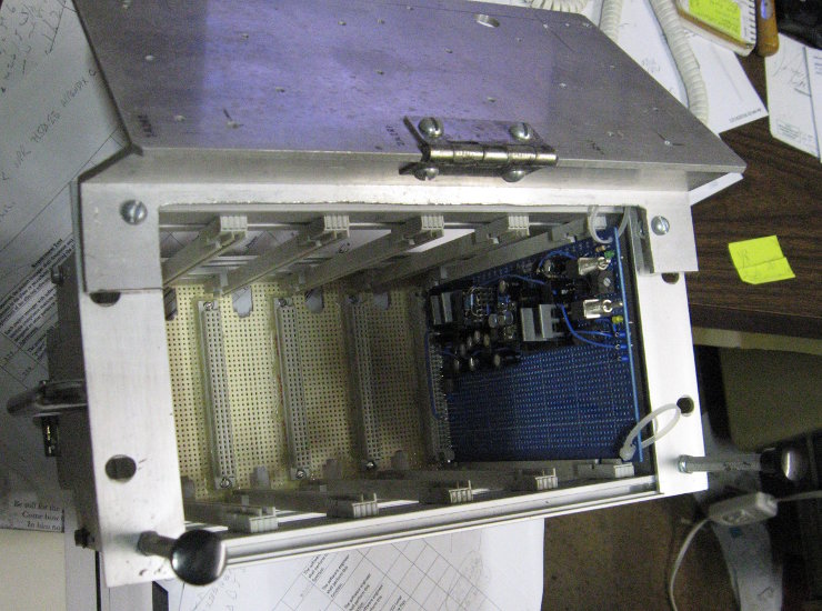
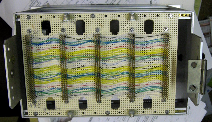
Then I found a half-rack-width 3U Eurocard card cage at an electronics swap meet years ago which I've started on. I started by putting a handle on the side, making a hinge-up front panel that protects the LCD, keypad, and fronts of the cards when down, but exposes them for use when up, then wire-wrapping a passive back plane, and making a rear panel to protect it and to hold a monitor speaker, batteries for when external power is not available, and connectors for RS-232, printer, audio, and power. (The connectors to the circuits being interfaced to on the workbench will be on the front edges of the cards.)
First here is the bottom, with the front closed and held down to threaded standoffs by thumbscrews, and then with the front swung up as will be the usual operating position giving access to the keypad and LCD:
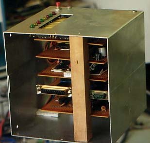
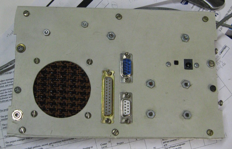
then the back, closed, and opened on its hinge:
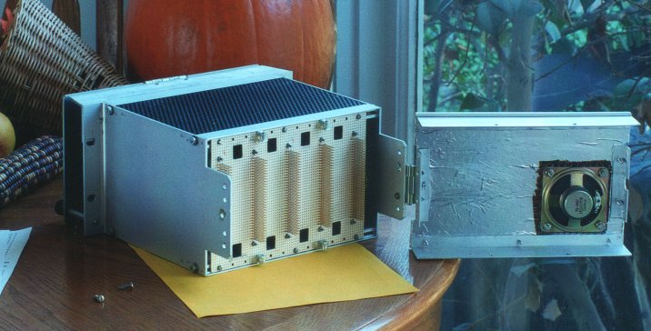
The back has the speaker, connectors, battery holders, and reset button in place but not wired yet:
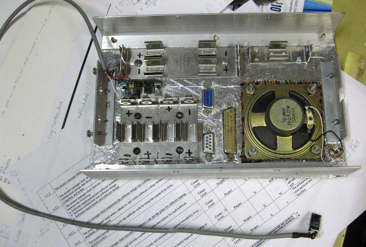
Here's the cage interior, with the completed power supply board in the right end (and half the board left available for additional supporting circuitry), and the wire-wrapped backplane with five 96-pin DIN 41612 WW sockets, placed at 1.6" centers, twice the normal separation, since I won't need many boards, and wire-wrapped ones need more space anyway, as do any boards with modules plugged in:
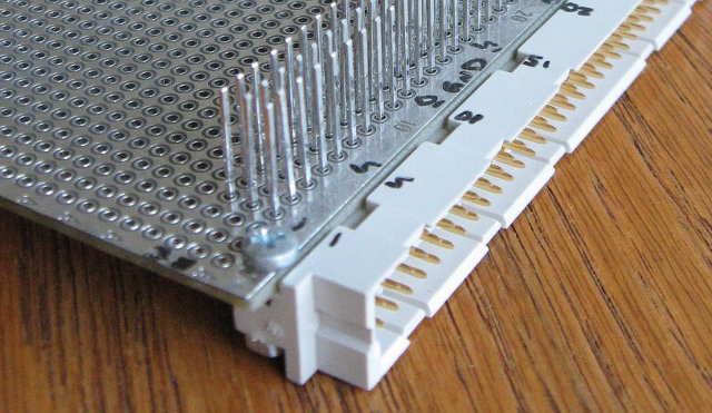
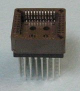
I have WW male connectors that go on the boards (this board has planes on both sides, so I can use one side for a ground plane and one for a power plane), and WW PLCC sockets too:
and of course the normal soldertail ones too for regular PCBs. A system that's on the market made after the same idea but much higher-priced and full rack width is that of National Instruments, with an example card cage shown here:
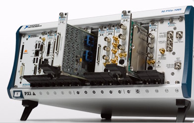
Using cards like this leaves the option to use the same ones in a smaller case later, especially if you only need one or two cards.
I have not started laying out or assembling the CPU board yet. The plan is to pre-load RAM from a tiny flash module before letting the processor out of reset, so there's no slow (E)EPROM on the bus, and the address decoding is simpler and faster too. I have laid out a little board with a microcontroller to do that, and now I need to write software for it and make sure I got everything right before I get boards made. I have some other projects I'm working on too though which have been causing delays. The plan is to use Jeff Laughton's circuit tricks to do several I/O operations in a single 65816 instruction.
Regarding what goes into it, I've made plan after plan, but threw most of them out after the years of experience proved these plans were either too grandiose to carry out in my lifetime, or unnecessary to accomplish what I wanted. Usually both. A set of VIAs and synchronous-serial ports goes a long way.
Note however that the processor's own buses do not go out on the backplane. Only I/O signals go out there,
to interface to other boards. The processor communicates with the backplane only through ports, whether
parallel, SPI, or other. I give the reasons for this at the top of the
"Expansion Buses and Interfaces" page
of the 6502 primer.
All the important hardware information (outside of data sheets for components) is kept in a small, very full 3x5" ring binder on the workbench for easy reference when I need to look up things like pin numbers for interfacing a new project, DIP switch numbers, jumper options, and which oscilloscope probe points are which. About half of the 80+ sheets (not cards) in it relate directly to Bench-1. (Others relate to Bench-2 and other project boards. Bench-3 has its own little binder waiting for it. :) )
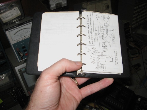
All the most important QRG (quick-reference guide) pages for Bench-1 are shown on the following linked page. I scanned them and tried to clean them up digitally (in Gimp) to make them more readable, as the writing is really tiny in places and I did not originally intend for others to have to read it, and also some of the pages have yellowed (or should I say browned, and unevenly!) such that making them black on white again and readable was time-consuming. You might often find yourself using <Ctrl>+ (or other method of enlarging the picture) to be able to read things; but you should find that all the needed resolution is there (just barely!). Bench-1's QRG pages are here. (I plan to have a separate web page for Bench-3's QRG pages in the future.)
Note that for something like this, putting the entire schematic on one sheet serves no useful purpose. It would be
like having an exploded view of a car's tail-light assembly in the same diagram with an exploded view of the brake master
cylinder. However, after many newbies' insistence, I finally drew up a diagram for an entire, minimal 65c02 computer,
at the top of the "Circuit potpourri" page
of the 6502 primer. That diagram is
followed by a lot of other things that could be added to the same computer; and in fact, Bench-1 is basically that diagram
(but with three VIAs and three ACIAs) plus the stuff following it!
Next--> Bench-1's QRG pages
last updated Dec 22, 2022