Before going into the next part of answering questions and doubts about wire-wrap, we need to briefly address the issue of expansion buses and interfaces.
Newbies have an excessive tendency to run the processor's own buses off the board onto a backplane or to other boards that plug in.
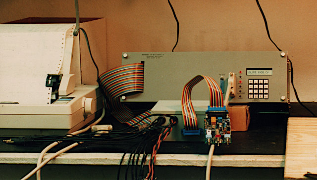
The tendency to build things this way is partly from copying the industrial card cages of past decades, when parts were slower and the fact that you couldn't get as much on a board meant you had to go out on the backplane to other boards for more resources. I took part in it myself, using STD bus (STD stands for "simple to design," not "standard"), and you can see one of the automated test equipment (ATE) setups I designed, built, and programmed at work. Here are three pictures; but see the link for more information.
Here it's all closed up. The wide ribbon cable goes to a test fixture box outside, which has one of our products connected by
a somewhat narrower ribbon cable, for testing:
The insides, shown with the front panel and cover removed: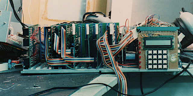
Operator interface: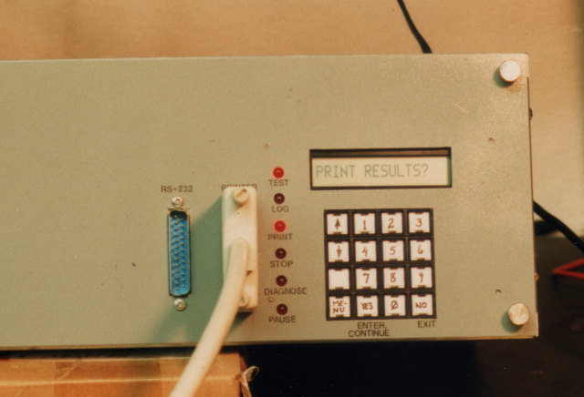
It was a good solution in 1990, but I don't think I would use it again at this stage. For one thing, STD bus would be impractical to try to interface to today's faster 6502/'816. Also, there's less need for that type of bus today than there was back then.
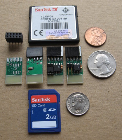
Take for example memory. At that time, if you wanted a megabyte of SRAM, battery-backed or not, it took a whole card. Now you can get more than that in a single IC socket on the CPU board. Back then, a disc-drive controller had to be on its own card also. Now, you can get far more storage in an SD card with the socket on the CPU board, or solder down a flash memory in a tiny SO-8 package.
The same goes for so many other things. It is no longer necessary to go offboard for much of anything anymore, which is nice because taking the processor's own buses off the board brings a huge performance penalty unless you're happy limiting yourself to a couple of MHz. (Sure, commercially made backplanes go far above that speed, but the design involves a lot of transmission-line theory which is not trivial. You can no longer just connect things and expect it all to work.)
If I cannot dissuade you, please at least follow this advice: Do not put all the power and ground connections at the ends of your connector! I address this in the "#4:" about 40% of the way down the AC-performance page, with the reasons why, but I'll repeat just the example diagram here to remind the reader:
The power pins should be bypassed to ground at the connectors, both male and female. Here, no signal pin is more than 0.2" away from a ground or bypassed power pin (assuming the pins are on a .100" grid).
What I advocate now after many more years of experience, as well as our now having a lot more SPI and
I²C parts on the market (see this forum post
for a concise comparison of popular synchronous-serial interface types), is not running the processor's own buses off the board
at all—not even buffered—but instead have several interfaces on the CPU board, including something like our
65SIB (6502.org serial interface bus) which
we devised on the forum, which extends SPI in several directions at once and makes it suitable for both internal and external
equipment and peripherals, both intelligent and non-intelligent, and works for SPI, Microwire, and dumb shift register devices all
simultaneously. (BTW, I have a 65SIB breakout board coming. Boards are made, but I need to build them up and test them,
and prepare the documentation.) Other interfaces on the CPU board might include LCD, printer, keyboard, I²C, Dallas'
1-Wire, etc..
I should add that in the ATE pictured above, only four of the boards were actually on the STD bus, and the STD backplane was only about five inches long. The other cards were controlled through a synchronous serial interface from a 6522 serial port giving hundreds of bits of I/O.
You might be surprised how much I/O and other features you can do with few parts if you plan it all right. One of the 6522 VIAs on my workbench computer is used for: (this list is repeated in the "I/O ICs" section, with the connection diagram)
That's all through a single 6522, simultaneously, and the only conflicts are that you can't press more than one key at a time while the LCD or printer are getting fed data or you'll mess it up, and you can't press a key during I²C operations. The connection diagram is in the middle of the I/O ICs page of this primer.
If you do use the I²C though, you can make tiny modules with a minimum of only four pins: power, ground, clock, and data. On
the forum, we defined a 6-pin connector standard called I2C-6
for I²C modules, adding the IRQ (interrupt-request-not) line which will be needed for
I²C devices like a keyboard scanner IC which could interrupt when a key is pressed, or a real-time clock IC that would interrupt when
an alarm comes due. (The 6th pin is cut off of the pin header on the motherboard, and the hole in the module's socket is plugged, to
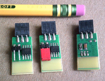
prevent plugging it in upside down.) In Aug 2022, I started offering this I2C-6 24xx EEPROM module you see on the front page of my
site:
Before we came up with the hobbyist-friendly I2C-6 connector, I had made up several similar (but only 4-pin) serial EEPROM modules that
are half the size of a postage stamp. One is pictured here:
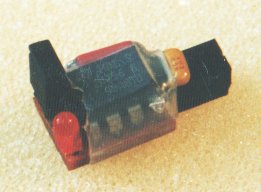
The shorting bar on the left is on a 1x2 pin header for write-protect. The LED tells when it's powered down so you can unplug it from the computer board, although after this first one I put LEDs on the computer to show the status of the I²C power and clock lines.
I have more I2C-6 modules planned.
In this forum post in the topic "Standardizing an SPI
module pinout: SPI-10," we have finalized a hobbyist-friendly connector and pinout for small SPI modules,
called "SPI-10." It is partially compatible with UEXT which also has
asynchronous serial and I²C and already has quite a few modules
available. UEXT however lacks 5V support, interrupts, reset, an auxiliary line, and keying for keeping non-IDC connectors from
getting plugged in backwards—all needs which are met by SPI-10. The middle row in this picture shows 4MB SPI-10 modules,
available on the front page of my site:
Making your project as modular as possible makes it more manageable, and makes it easier to recover when you change your mind. (I started my on-the-side home business, Wilson Mines Co., to make modules for this purpose—not a money-maker, but to help hobbyists without breaking any tax laws.) Anyway, there's a lot of I/O bit sharing you can do on the I/O ICs.
I haven't done things like SATA, but my workbench computer exists for workbench I/O, not human I/O, and everything goes through three 65c22 VIAs (and three 65c51 ACIAs which get very little use). These are all on the main board. The things mentioned above go through the first VIA. In addition there are the
It does have a board-edge connector plus a mezzanine board, but the processor's own buses don't go to these! If I want to add USB or so many other things, they are available in SPI or other interfaces that can go through ports I already have.
SPI can be handled at high speeds through Daryl Rictor's 65SPI chip (a 65-family SPI I/O IC, not to be confused with 65SIB which is the super-flexible interface method). (Note: in 2018 the CPLD he was using to make version 1 of the 65SPI was discontinued, so he migrated the design to a newer one, the Atmel ATF1504, for version 2. He is not currently selling pre-programmed ones, but the source code and object files are available at the link. I hope someone will take it up and supply finished parts.)
Bit-banging SPI is very easy, and although slower, is still plenty fast for most uses. I have sample code, in several forms, here. For the things that need the very fastest access like maybe video, put it on the same board with the processor. SPI can be almost as fast (actually, the fastest SPI ICs I've seen will handle nearly 200MHz SPI clock rates). I²C is slower but nearly the least work to hook up is good for things that don't need as much speed or don't transfer much data, for example, a digital temperature sensor or real-time clock or keyboard scanner which isn't going to change readings thousands (let alone millions) of times per second. I have a pros-and-cons comparison of SPI versus I²C in this forum post, about 2/3 of the way down the post, at the bulleted list.
These serial parts make a project far more manageable, since there are so few connections to make. Otherwise you begin to realize you may not live long enough to carry out the project you had envisioned. (Been there, done that.) I am constantly encouraging people to take advantage of the thousands of synchronous-serial ICs on the market.
Now after all that, if you still want a parallel I/O expansion bus, there are additional guidelines in the first three paragraphs of
this forum post and the ones around it.
construction for AC performance <--Previous | Next--> get more on a board
last updated Aug 5, 2022