Because of the processor's state machines mentioned earlier, you must purposely make it start out in a known state to begin orderly operation. This is what bringing the RST (say, "reset-not") pin low and then back high does. It must be held low for a bare minimum of two full clock cycles. If the computer is just powering up, you cannot start counting those clock cycles until the clock has reached stable operation, putting out a strong, clean square wave on the right frequency. After the reset signal comes up, the processor takes seven clocks to set itself up internally before starting into your programmed reset routine. The reset sequence includes reading addresses $FFFC-FFFD to find the real address of the beginning of the reset routine where it should start executing. Later we'll discuss what should be in that routine.
To answer an important question that came up on the forum 3/25/25: The RST input does not care what the phase of the clock is or how the edges relate to each other timewise. I have always disregarded phase and timing on it, and never had a problem. Just heed the material on this page, and you'll do fine.
Just putting a pushbutton on it with no debouncing is not guaranteed to be adequate. Switches have a lot of "bounce;" meaning that when the contact is made or broken, it is not suddenly just "on" or "off" and just stays on or off. It will go off and on, "bouncing," for a few milliseconds, and the number and widths of the bounces could be just about anything. If the last low time on the reset line is less than the minimum the processor requires, it may not get a complete reset; and what it does after that is anyone's guess.
At least some of the CMOS 6502's have Schmitt-trigger RST inputs; but for this writing, I was not able to find out which ones. Certainly not all the I/O ICs do. There are many ways to get a clean, single, fast rising edge for a good reset signal. Just putting a resistor and capacitor on the RST input won't do the job for ICs that don't have Schmitt-trigger reset inputs.
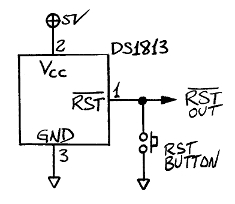
The Dallas Semiconductor (now part of Maxim) DS1813 3-pin IC in a 3-pin TO-92 case is a nice, compact integrated way to manage the reset. Connect it this way:
An external 3.3K pull-up resistor is often recommended; but note that the DS1813 already includes a pull-up internally, which the data sheet says is typically 5.5K, and may be as low as 3.5K and as high as 7.5K. In many cases there won't be any need to add an external pull-up.
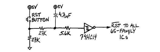
If you've been working with other digital stuff and already have a 74HC14 in your inventory, the following circuit debounces the reset button and gives a clean, fast rising edge on the reset signal, without any special reset ICs:
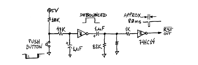
Now if you really must use an old NMOS 6502 (I don't recommend it), you should be aware that some early NMOS 6502's had an internal heating problem that could damage the part if the reset line was held down very long. It was recommended that you not hold it down more than about a tenth of a second. The following circuit debounces the button and produces a reset pulse of about 80ms. You might recognize it from earlier in the Clock Generation section where it was used for single-cycling; but the values have been changed to increase the low time from 1µs to 80ms. The exact times will depend on not only the values in the second RC (shown to be 1µF and 82K here) but also the size of the hysteresis of the second Schmitt-trigger input.
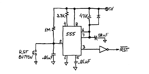
Some computer manufacturers used the popular 555 timer IC in their reset circuit. The following is approximately what the Sym-1 used:
clock generation <--Previous | Next--> mystery pins
last updated Mar 25, 2025