WW still has the advantage in being able to modify or augment, which also means there's less of a need to have an entire schematic done before you start building. Also, compared to a thru-hole PCB with DIPs, WW still has the advantage in density, since you can put sockets right up against each other with no space in between, and you can still get everything routed.
Now as I edit in 2024, I'm 80% through laying out a multilayer PCB for another workbench computer, and by far, the hardest and most frustrating part (and why the project was backburnered for years) has been that of trying to make all the desired I/O connectors, LEDs, and switches available at the front edge, for the option to put it in a card cage. It's been difficult even with a mezzanine. I didn't have this problem with the existing workbench computer which was wire-wrapped; because after getting it going in its initial version, I added things as the need arose, and where they'd fit, and I could back up and unwrap something and try again without starting over. The reason for laying out a board this time is that I want to make several; but in all the time I've spent laboring over this design, I could have wire-wrapped several boards!
There's an impressive demonstration of dedication in the last quarter of the page at http://www.homebrewcpu.com/photo_gallery.htm showing this man's home-made minicomputer, definitely no slouch!
Q. Why not use soldertail IC sockets, and solder fine wires (even WW wires) to make the connections?
A. The solder-type breadboards with three to five holes per pad work well for analog with its many discrete components, but they don't do well for digital work where most parts are ICs and the connections are long and bused. Long connections are bad for high-speed performance, especially if they're not against a ground plane.
Even with single-pad-per-hole perfboard (which makes it harder to get two or more wires on a pin), you have to make the wires longer, either to go around parts on the component side, or, if on the solder side, so you can move them as you access subsequent points with the soldering iron. The movement of wires promotes breakage at the solder joint. But if you wire-wrap (correctly), they won't break. WW lets you put many wires on one pin, even after the pin is surrounded with lots of other wire "traffic" going past it, between it and the next pin. You won't damage previously placed wires or their insulation.
You generally want the connections as short as possible. Putting IC sockets right up against each other helps, but you can't do that if you have to allow room for a soldering iron, or if holes are connected together in groups on the board. For the few discrete parts involved in a computer breadboard, you can usually solder them either directly to socket pins on the back of the board (after having done the wire-wrapping), as in the case of connecting a crystal or a bypass capacitor, or put them on DIP headers that get plugged into IC sockets.
The thinner board profile afforded by soldertail sockets may be attractive, but WW pins only add about 3/8" to the overall thickness if you use common 2-level sockets (which actually can take 3 wraps if you do it a certain way), and WW also lets you get the circuit in less board area.
I started out with soldering wires to soldertail sockets myself. I had to learn the hard way.
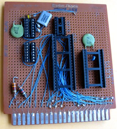
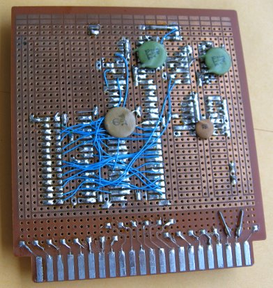
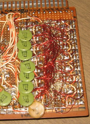
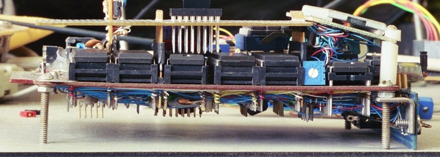
How not to build digital circuits:
The density is poor and the wires are long and curved, which is not good for high-speed performance.
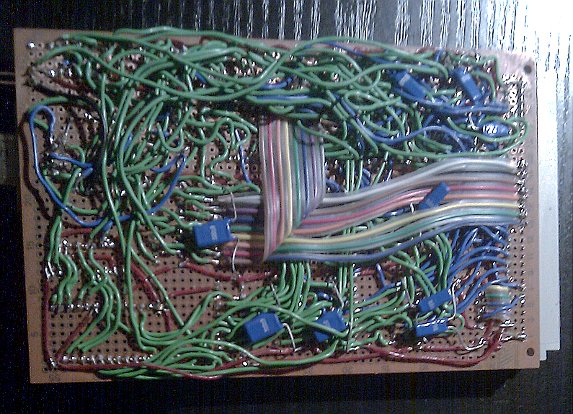
The first three were in my first home-made computer with a 1MHz 6502 and slow parts though. The last one
is someone else's and he gave me permission to show it for this. :)
Q. Isn't wire-wrap unreliable?
A. Not if you do it right. In the thirty years I've used WW, I've never had a wrap fail. It has been 100.00%
reliable. I may be more meticulous than I need to be, but it gives peace of mind. With good workmanship, the gizmo will last
longer than we'll be around. The whole idea is that tightly wrapping clean wire on clean posts makes a chemical weld at each corner
of the post. These are unaffected by oxidation on the outside of the spiral, however ugly it may get over the years, as well as
unaffected by vibration. If you unwrap with the tool (as to fix a mistake or make a modification), with a careful touch you
can sometimes feel the tiny welds breaking. It gives confidence that there's more happening here than just metal touching metal.
Q. Do you solder after that?
A. No. There is no need, even if you want it to last for decades. The WW failures I've heard of were always a
result of sloppy work. The only wraps I solder are where the post is not a standard .025" square post. One example is LEDs,
where the smaller (albeit square) lead may mean the tool doesn't really make the corners bite into the wire and make a gas-tight connection.
Another example is round-leaded devices if you wrap wire onto them. I don't recommend wire-wrapping those though unless the leads are fairly
thick and stiff. (See the next Q&A.)
Q. So what about discretes which don't go nicely into WW sockets?
A. In a very few cases, you can solder them directly to the pins of a socket, like the 1.8432MHz crystal of a 6551 ACIA, or the bypass
capacitors from Vcc to ground. Or, for just a component or two, you might cut the component's leads pretty short and solder the ends of WW wires
them without wire-wrapping. Another method is to press purpose-made WW pins into the holes, solder the components to the pins, then
wire-wrap the pins. Shown here are Vector's T44 and T68 pins:
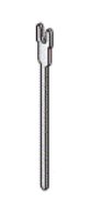
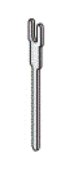
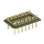
Again, be sure to get the skin oils off them before wire-wrapping. If there are more than just a couple of components, the better thing
to do is to put them on a DIP header which can be plugged into a WW IC socket. You can even glue a cover over the DIP header if you like,
so the size and shape is like a socketable relay. Shown here is a 14-pin DIP header, ready to solder components onto:
Q. Do you trim the leads to make the board fit into a nice, slim case?
A. No. If there were room to trim, you'd have to make sure you could trim all of them anyway or you wouldn't
save any room. Trimming may also alter the shape at the end so much that you can't use the tool on it again for future corrections or
additions. See also the answer after "Isn't protecting the pins a problem?" for pictures.
Q. What tool(s) do you use and/or recommend?
A. I've only used two wrap tools. I started out with the Radio Shack tool which looks like a jeweler's screwdriver
and is apparently the same one that Jameco's part number
2150361 shown here

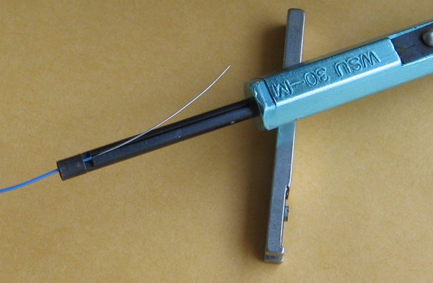
but I didn't have a very good success rate. Then a friend recommended the OK Industries WSU 30-M. (Although it says "WSU 30-M"
on the tool itself, you might need to type "WSU-30M" into a distributor's search bar.
I don't know why the discrepancy.) He was quite a WW veteran, and that was his favorite. It has a blue-anodized hex handle
with a 1.25" shaft on one end with the wrapper, and a 3/4" shaft on the other end with the unwrapper. He was trying out an
electric WW tool at the time, but was not happy with the results. I do still use the stripper that came with the Radio Shack tool,
even though there's one built into the WSU 30-M. The shorter one that came
inside the handle of the Radio Shack tool has the stripper part right at the end, so I can wrap the first end of the wire, bring
the wire over to its destination and see exactly where to cut and strip, and do so even if it's really short and there's not room
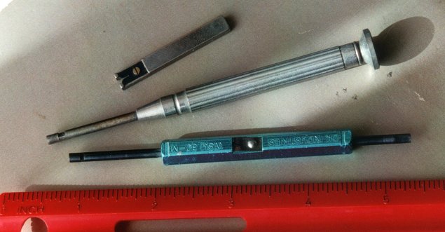
to use the WSU 30-M's stripper. The WSU 30-M (or WSU-30M) is the small blue one near the top in this picture:

Here are the two together, showing the separate stripper that comes stowed in the handle of the first tool:
Noticed on 12/7/22: The JDV HSR30 sold by Jameco here appears to be the same as the blue WSU one above. If you can't get the WSU, or just decide to try the JDV anyway, let me know how it works. Another notice, 11/27/24: The GCP-030 sold by Jameco here appears to be a closer match.
Q. So you don't use the pre-cut and -stripped wires?
A. No. For reasons discussed earlier, I cut every wire to the minimum length needed to reach its destination without
tugging at the pins. Also, since reliability depends on cleanliness, I want to strip the inch of insulation off the end immediately
before wrapping, so that there's no chance of its oxidizing or getting contaminated with skin oils or anything else.
Q. What if the wrap process has a problem, or you make a mistake. Can you unwrap and re-wrap?
A. It can be done if you're careful. Unwrap with the unwrapping end of the tool, and straighten the wire out with tweezers (without touching it with your fingers). At first I didn't know if I could trust the process; but as you gain experience, you'll be able to tell by feel if it's not going on right, and especially in the case of re-wrapping, if there's any tendency for the wire to break. In some cases you'll have to replace the wire; but usually re-wrapping will work.
If you have to have many pins daisy-chained, it's good wrap pairs this way: _¯_¯_¯ etc., not \\\\\\. In other
words, connect 1 & 2 with a wire, then 3 & 4 with the next wire, then 5 & 6, then go back and connect 2 & 3, then 4
& 5. It can make corrections easier, depending on how well re-wraps go.
Q. Do the sockets need to be fastened to the board?
A. Not really. With many perfboards they will stay in snugly enough to prevent falling out when you turn the board
over to wire-wrap; but in most cases, you can just use the wire wraps themselves to hold the socket in. There have been times that I
used a little hot glue on the top to hold sockets in before they were wire-wrapped, or, in the case of perfboard with pads around the holes,
soldered two pins at opposite corners. If you do solder, make sure the solder and flux are confined to a small area very close to the
board so they don't interfere with the pins' sharp corners biting into the WW wire when you wrap later. When I install WW pin headers
which may handle quite a bit of force to unplug the IDC or other socket that plugs onto them, I do solder the pins to the pads on the board
before wire-wrapping.
Q. I've never done this. Where do I start, and what should it look like?
A. If the WW sockets have been touched, then before you insert them into the breadboard, wipe the .025" square posts between layers of a clean paper towel tightly pinched in your fingers. After that, mitts off! That is, don't touch the sides of the posts with your fingers. (Touching the tips of the posts is ok.)
Strip nearly an inch of insulation from the wire, and then don't touch the bare wire with your fingers.
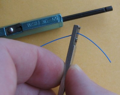
Insert it into the end of the tool, near the edge so it goes up the groove cut in the side. The end of the insulation should stop when it has gone in about 3/16" (4mm).
Put the tool with wire inserted down over the .025" square post, and turn. I wish I could give more detail here, but you'll get even the less obvious parts figured out with a little experience. Perhaps later I can post a video...
There should be about a turn and a half of insulated wire wrapped on the post (although the exact amount is definitely not critical), mostly so if you have any motion on the wire before completion, you don't get a lot of fatigue right where the wire exits the insulation. The WSU30-M tool mentioned above automatically wraps a portion of insulated wire. The yellow WSU30 (without the "M" on it) does not, so get the one with the M. The insulated part of the wire doesn't have to be in contact with the post itself, so after the first wrap, I wrap the insulated part of subsequent wires over a previously wrapped wire. This helps me get one and sometimes two more levels of wrap on the post than it was made for, and probably helps protect that previous layer from getting peeled away at the end too. It does not add significant inductance like a coil usually would, since it is wrapped over a good conductor which would collapse the magnetic field the "coil" tries to set up.
With most tools it won't matter if you go clockwise or counter-clockwise.
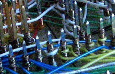
As you can see in the pictures, the outsides of the silver-plated wires' wraps eventually get very tarnished, and it turns black; but the area of the actual chemical weld is immune to this. The wires that are copper-colored here are not Kynar brand. They have a very different feel when wrapping, requiring a lot more pressure, but I have not experienced any evidence that they're any better or worse than the more common Kynar type, except that the insulation quality is not as good (which is mostly unimportant unless you have to solder one end of the wire where wire-wrapping is impossible.) The board on the left was wire-wrapped about 15 years before the picture was taken. These were done with the blue hand tool in the pictures further up.
Good wire-wrapping relies a lot on the senses. What does it feel like is happening inside the tool? Is the tension consistent?
Can you feel the end of the insulation landing in the right place? Is it binding? Can you feel the previous turn under where the wire is
currently being laid? The Kynar and the cheaper copper wire have very different feels, but I like them both. When you're new at
it, you may tend to have wraps whose layers are not together and wraps where layers overlap. Especially the overlap is no
good and needs to be redone. Wire-wrap tools tend to have sharp areas in them when they're new, and you may accidentally cut the
wire sometimes at first. Just keep at it. Both you and the tool will improve.
Q. What is the typical pin length on the sockets you use?
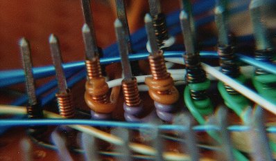
A. Many sockets are hard to find in 3-level so I mostly end up using 2-level. These protrude from the board surface
around .4", give or take a little depending on the manufacturer. As I mentioned earlier, wrapping the insulation over previously wrapped
wire lets me easily get three levels of wrap on a post. 2-level is what you see in the last two pictures above, and you can see that
wrapping this way, it's no problem to get three wraps on them. 3-level posts are probably good for 5 doing it this way— just don't
plan on removing the bottom one unless it's okay to just cut the wire off!
Q. Where do you purchase wire-wrap sockets and materials, and what kinds?
A. I've gotten most of mine from Jameco, but any catalog of that
type (DigiKey, Mouser, etc.)
will have it. Jim-Pak (part of Jameco) is carried by many local electronics stores, and even Radio Shack has some WW supplies.
(Even though most Radio Shack stores are gone, you can still buy from Radio Shack online.) WW sockets are definitely more expensive
than double-wipe soldertail sockets, espcially now that WW has lost the economy of scale it once had; but you may find the dollar price is
quite acceptable when you consider it against the amount of time you put into the project. The Kynar 30-gauge wire is perhaps the
most common of the high-quality WW wires. It has a very smooth feel, and the insulation is quite tough and heat-resistant. I
buy the wire on the 100-foot spools. I get as many colors as possible. This makes it much easier to follow what I've done
than having one big pile of white wires. I'll use different colors for the data bus, address bus, I/O, select and control lines,
power, ground, etc..
Q. Isn't protecting the pins from getting bent a problem?
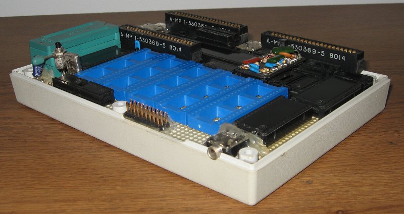
A. There are different ways to do this. If the board doesn't have to be very portable, I put screws through the corners to act as feet so the board never rests on the pins.
(The above picture was taken when there was nothing on my mezzanine board yet except a 3-level WW socket to show the clearance.) Obviously additional means would have to be taken if you wanted to throw the board in an attaché case. That can be accomplished by mounting the board in an ABS plastic box. Even if you only use the bottom of the box and not the top, at least the pins are protected. Here's an example, although I never finished building this one:
When you take it out of the base of the ABS plastic box, and turn it over, you get:
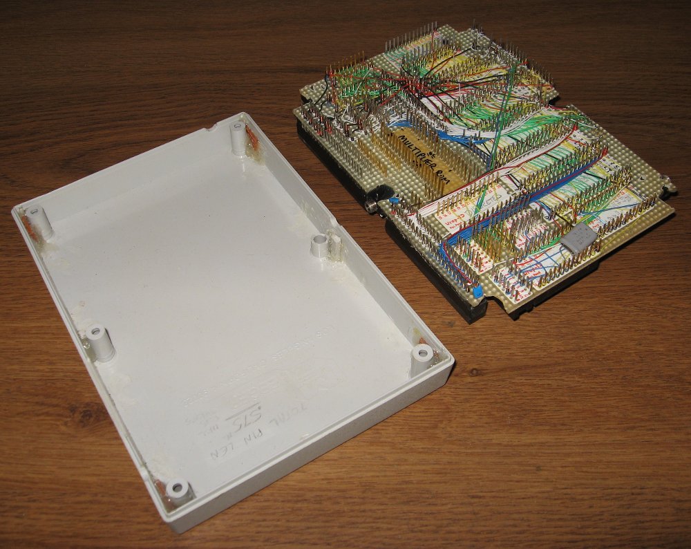
You can see the pieces glued into the corners and the middle of the sides of the box, to hold the main board up at the right height, making the connectors line up with their holes in the box, and keeping the pins off the bottom. ABS is great stuff for milling at home with a Dremel rotary tool. This is one of the computers shown in my (outdated) project pages on 6502.org.
I don't use a machine myself, but if you do, you might find http://www.tecratools.com/pages/tecalert/wirewrap_guide.html helpful.
get more on a board <--Previous | Next--> custom PCBs
last updated Nov 27, 2024